Hey folks! Another interesting topic to discuss and share! Integrating sensors to an Arduino board seems interesting and feels good when you receive the desired digital output and manipulate it. Now a days hundreds of different kinds of sensors are available in the market, we need to try out and explore how we can better user experiences using these electronics. Temperature monitoring sensors, obstacles detection sensor, soil moisture detection sensors, heart pulse rate sensors and many more. I will try and use as many as sensors as I can and try integrating them with more sophisticated devices. In this article I would be sharing about the IR Obstacle sensor, which as the name suggests detects object or any obstacle coming the sensors way! Lets see how.
The sensor
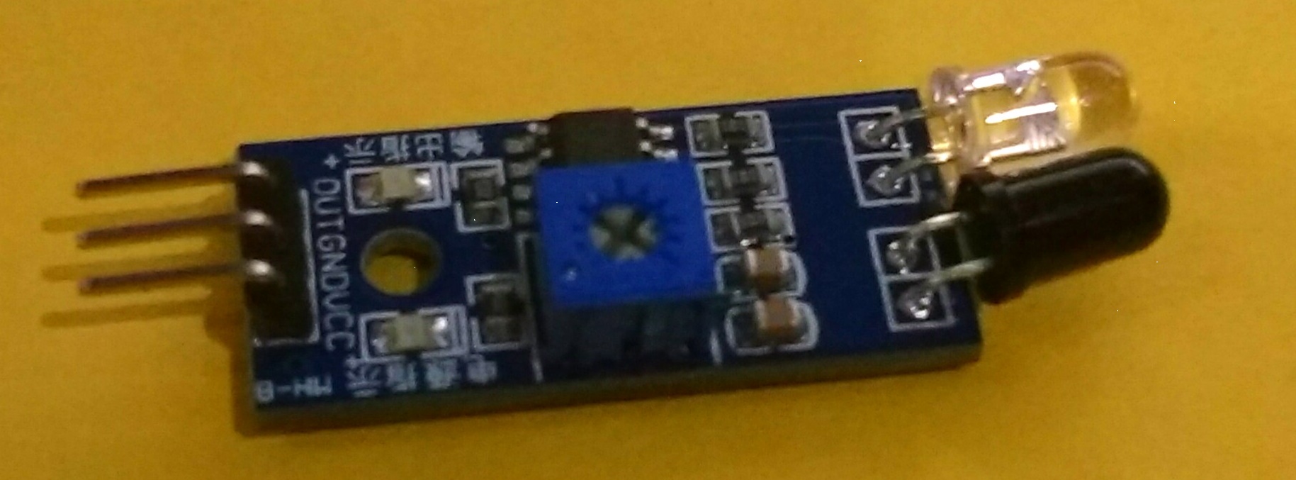
Here is how the sensor looks like. We will see another pictorial representation of the above sensor and discuss about the details of the part.
The pictorial goes like below:
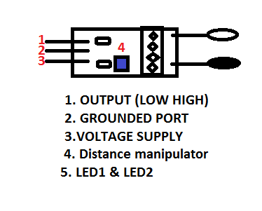
Lets learn and see what the sensor has. As you can see the numbers are mentioned, we will discuss the work around and try understand each and every word. First one goes like:
| Sensor Parts | Functions |
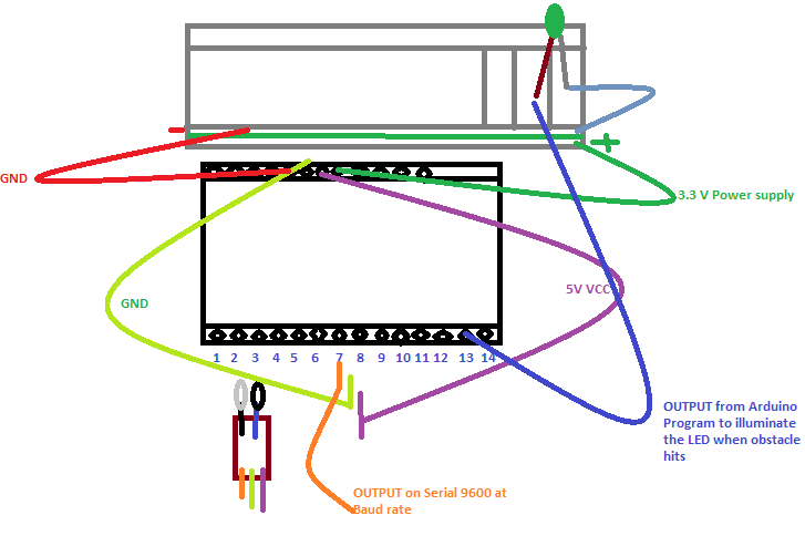
| OUTPUT | This port in the sensor, sends the digital out put to the output unit. Here, we have the sensor output port on board as 7. |
| GND | This port is used to connect to the board’s Grounded port. |
| VCC | The voltage supply port, here we have used the 5 V supply port from the board. |
| Distance Manipulator | The CW (Clock wise) movement increases the distance proximity and the vice-versa decreases. |
| Power and Obstacle LED | Former illuminates when the Power is supplied and the latter when any obstacle comes over. |
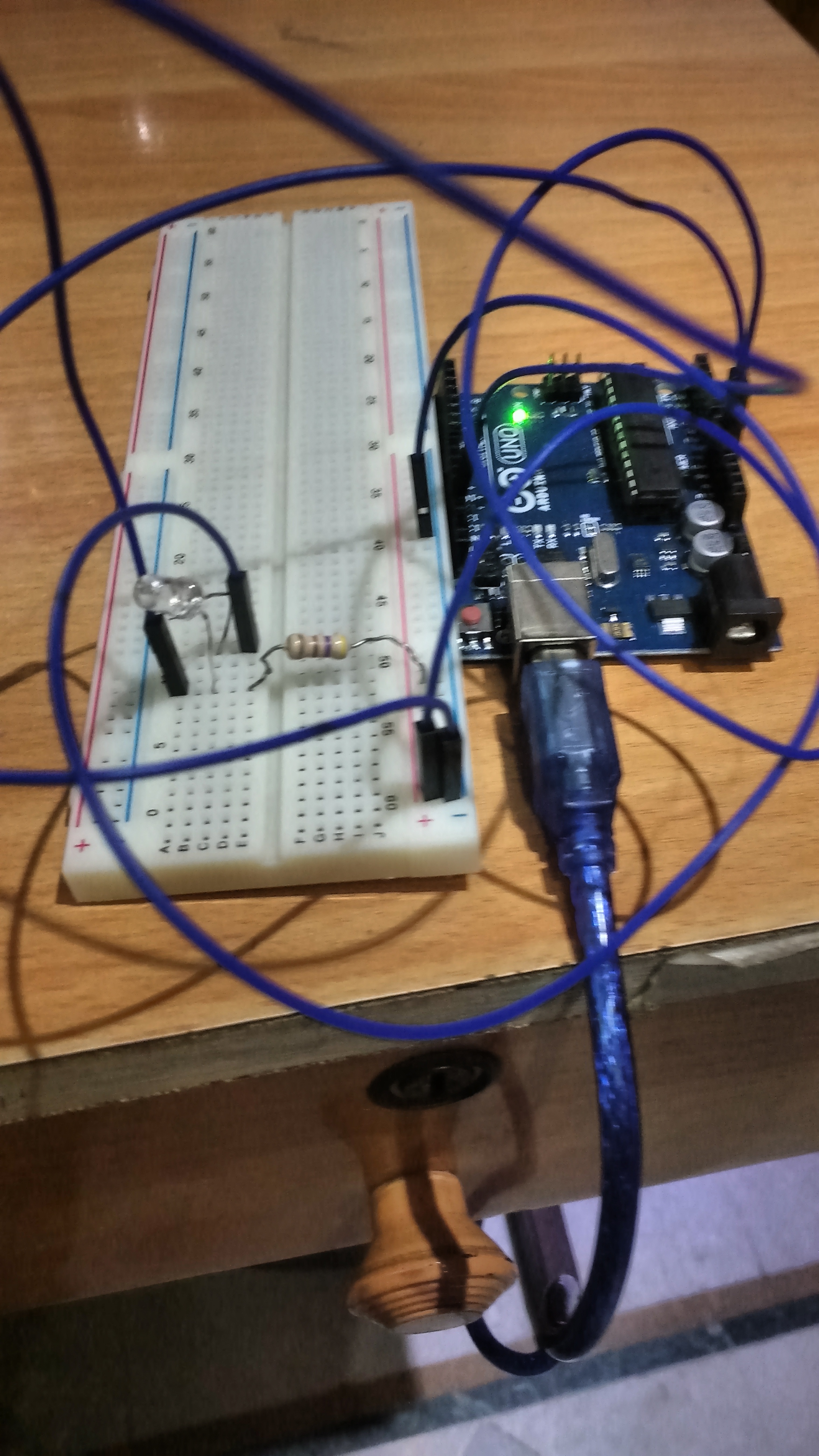
The circuit board looks like below:
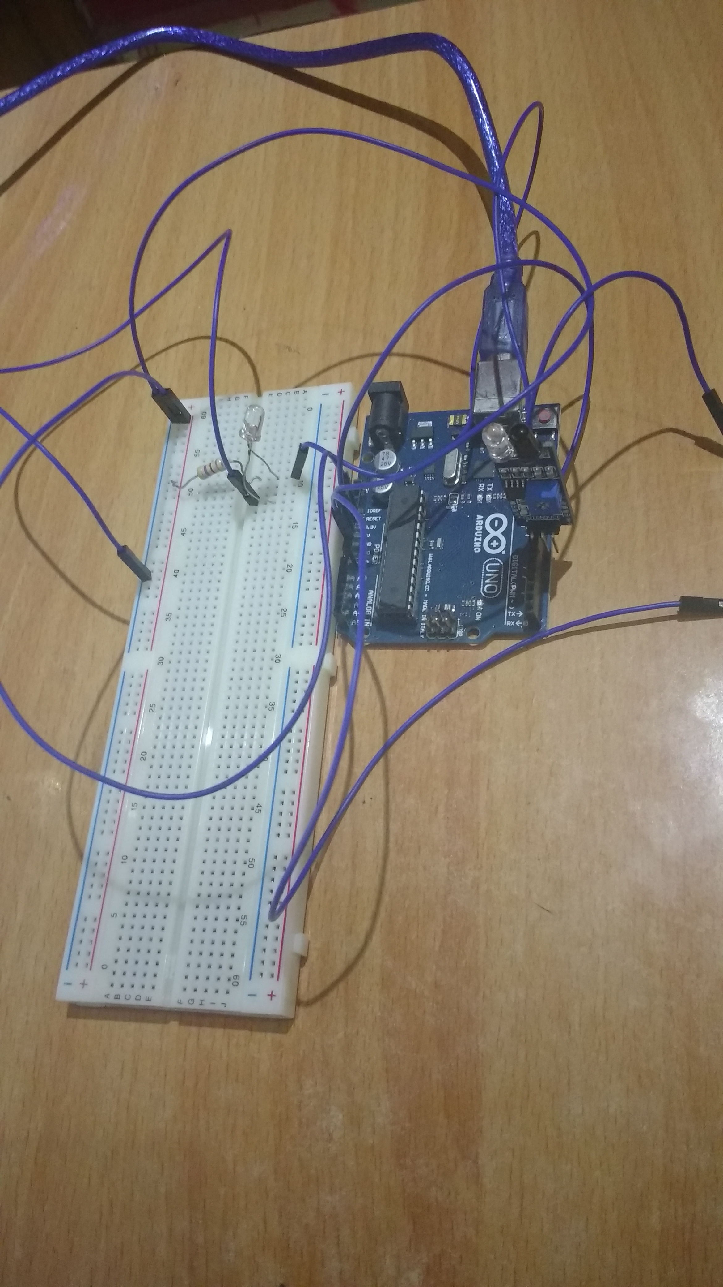
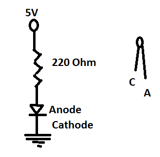
The circuit diagram would look like below:
Thats similar to the previous LED connection of my Arduino series. Series I
If the above is not clear, please share your query in the comments.
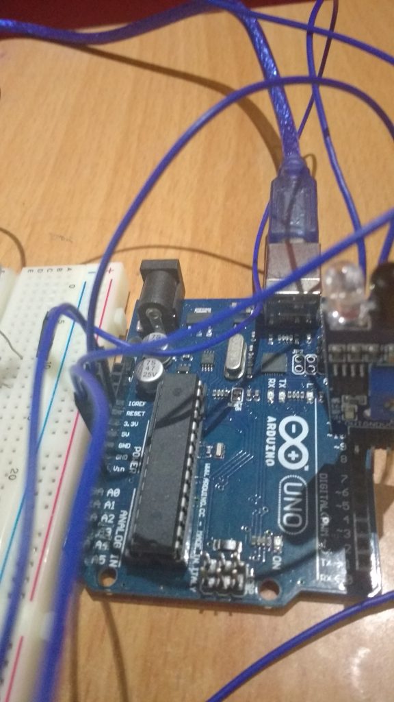
Better view of the diagram is below:
Snippet
int LED = 13; // Use the onboard Uno LED
int obstaclePin = 7; // This is our input pin
int hasObstacle = HIGH; // HIGH MEANS NO OBSTACLE
void setup() {
pinMode(LED, OUTPUT);
pinMode(obstaclePin, INPUT);
Serial.begin(9600);
}
void loop() {
hasObstacle = digitalRead(obstaclePin); //Reads the output of the obstacle sensor from the 7th PIN of the Digital section of the arduino
if (hasObstacle == LOW) //LOW means something is ahead, so illuminates the 13th Port connected LED
{
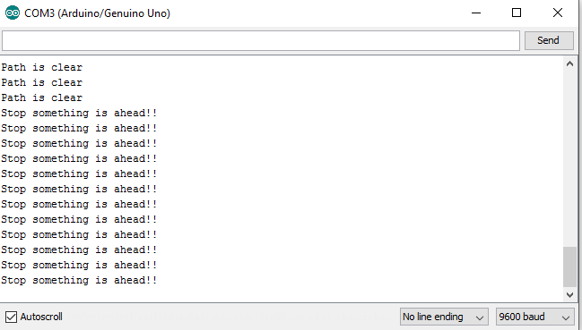
Serial.println("Stop something is ahead!!");
digitalWrite(LED, HIGH);//Illuminates the 13th Port LED
}
else
{
Serial.println("Path is clear");
digitalWrite(LED, LOW);
}
delay(200);
}
The Flow
When the full circuit is done and the code set is also done. Now, time to connect the Board to the Computer using the USB jack. Once connected to suppose COM3 port, open the Arduino Set up IDE where the code set up is done, compile the code once and then Upload the code to the Board. Once Upload is done the TX RX leds blinks quick.
Now we are all set to test the sensor. For better and precise testing, we can solder the wires (jumper wires) to the sensors as their connected pins are not portable. The whole set up can be soldered.
Then when we connect, open up the Serial port screen which transmits at 9600 bits per sec and check the message, as per written in the program.
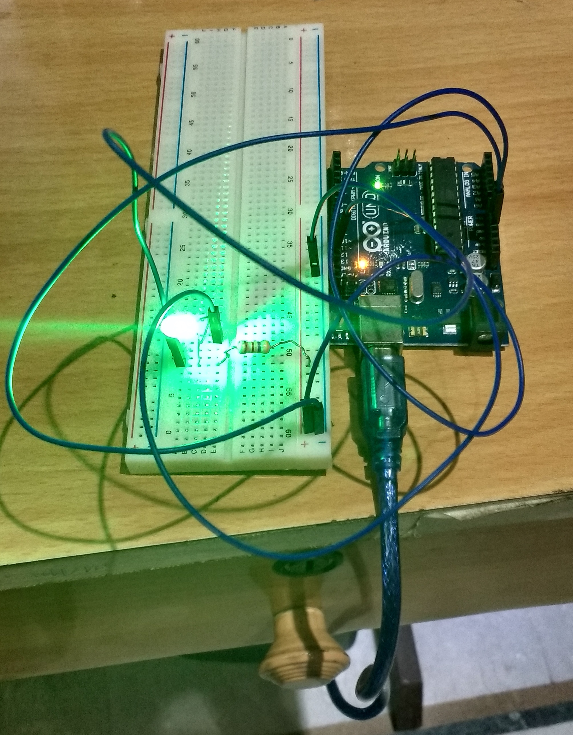
As per the program, the LED also blinks and illuminates based on the Obstacle sensor output.
The serial screen would look like below:
That’s it folks!!
Conclusion
Now this is all about the sensor IR Obstacle sensor which you can purchase at a very cheap rate from ebay or amazon and play with. We can use this set up in our Cars and check out!! In the upcoming series I will be sharing more sensors and blue-tooth module integration with Arduino. Hope they will be more fun! Please share your experiences and suggestions as I am still crawling..:P
]]>Being a Web application developer and with the huzz buzz going on around about IOT, I felt left out way behind in the crowd. So, I decided to start my journey on learning the IOT. Since I am a baby in this arena, I would keep sharing my crawling experience as I believe there would be many who would be waiting to crawl.
I have decided to use ARDUINO board in order to start my learning experience. Why!! Because it is economical, easy & has its own IDE to let us write the code and upload to the board. Lets learn something about Arduino first.
ARDUINO
Arduino is a simple micro-controller which is based on input output receiving unit. We can have it attached to any sensors, leds , switches etc. The best part is it is open source and easy to understand use. You can also contribute to the arduino community, creating your own prototype programming. For beginners, Arduino is the best option, I would say!
To get started with, you would need an Arduino Board first.  So get it online at a very minimal rate, for around Rs.500 (Indian currency!). I would be using Arduino UNO board.
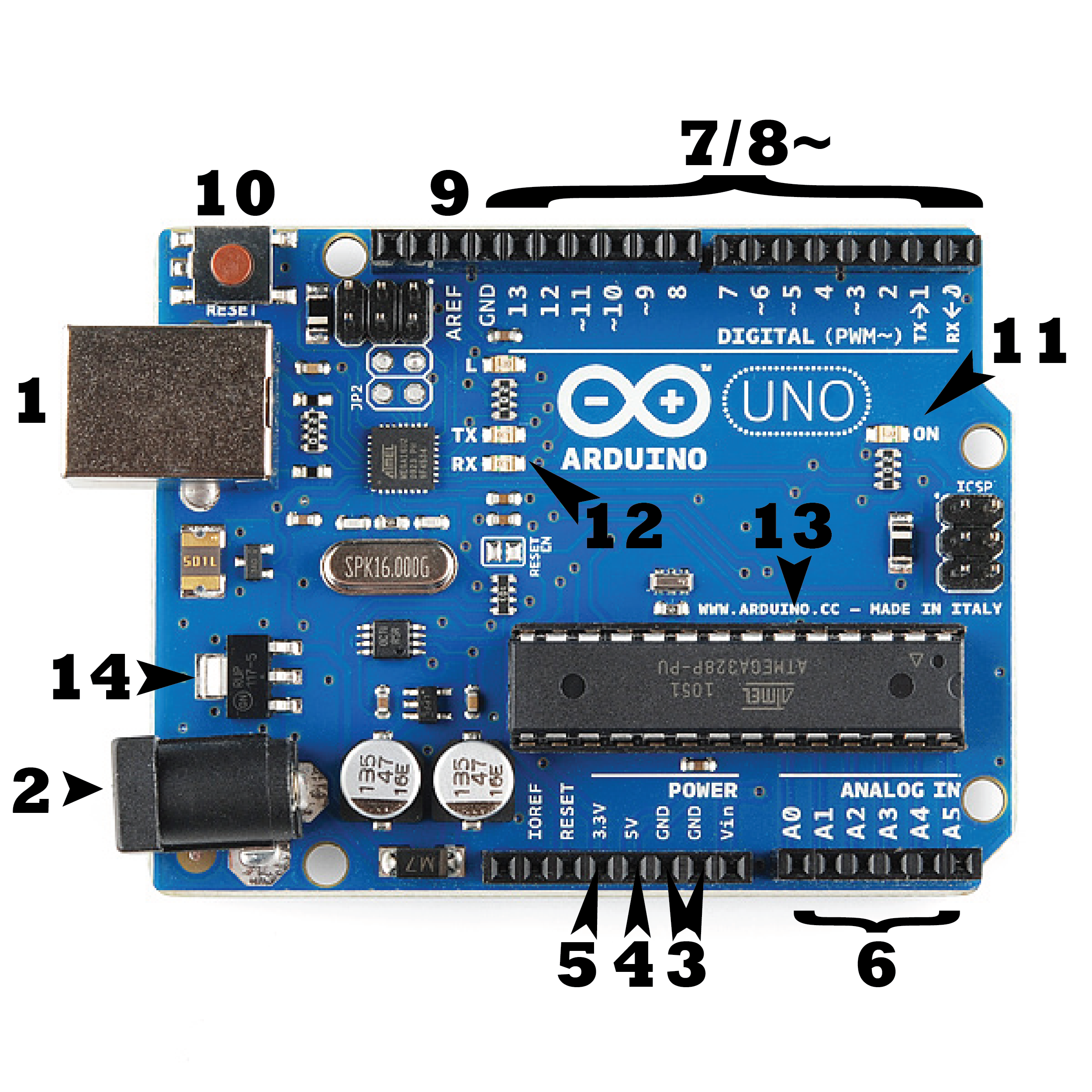
The above is the simple Arduino Board which does miracles. Lets understand the points mentioned in the diagram and their usage!
- 1- USB Jack:- This is the connecting female port, where the cable gets inserted in order to set a connection to the computer to have the IDE accessible and upload the programs.
 .Usually it is 2.0 USB port. The input and the output passage happens through this, we can consider this to be the starting point of the Board. usually the voltage acceptable is
Input Voltage (acceptable)- 7-12V
Input Voltage (limit)- 6-20V - 2- Power Jack:- As the name suggests, it is the external power supply. But be careful while using this, use a multi meter to check for the acceptable limit of power to be transferred to the board in order to avoid short circuit.
- 3- GND Pins:- The grounded pins used to connect the jumper wires to have a grounded circuit. Usually, when we see the connection we will realize that gnd pins are considered as the negative supply.
- 4- 5V Supply:- This is the point used to have the bread board 5V supply in order to power the circuit, which we will check out in a few moment.
- 5- 3.3 V supply:-This is the point used to have the bread board 3.3V supply in order to power the circuit. Same as the 5V but based on our circuit requirement we can also use this in case we are missing resistors.
- IOREF:-Though not numbered in the diagram, this is an interesting port in the board, which provides the voltage ref. with which the microcontroller or the arduino board operates.
- Vin:-As discussed above about the external supply to the board, to pass the voltage to the circuit (external), we can use this port.
- 6- Analog Input Pins:-These are the analog points in the board, which would help convert analog inputs to digital. usually used to read analog signals.
- 7,8,9- Digital Pins:- The digital pins which provide the circuit the uploaded code to connect(layman terms). Used for digital I/O
- 10- Reset Button:- It is self explanatory, used to reset the microcontroller or the board.
- 11- ON:- When connected to the USB, this green led lids up to let us know the board is powered.
- 14- Voltage Regulator:- The voltage regulator supplied to the Arduino board.
- 12- RX-TX LEDs:- These are the LEDs that lid up when the code or the program is successfully uploaded to the micro controller. This is the practical implication I have come across so far!

For more info on the pins please refer Arduino Pins
So this is it about the Arduino board, a brief summary I would say1 There is much more to this. Please refer here
Some Pre-requisites
Here are some pre-requisites required to learn and start on the work with the Arduino. After you get the Arduino board from market, next job is to install the Arduino IDE on your system in order to interact with the microcontroller.
To install the IDE visit the link:- Arduino IDE Download. Here, you get a list of OS where you can install, this proves it is cross platform1 :O Wow!! another great feature!
After the installation, you need to connected the USB jack to the computer via the jack cord and get the Arduino connected.
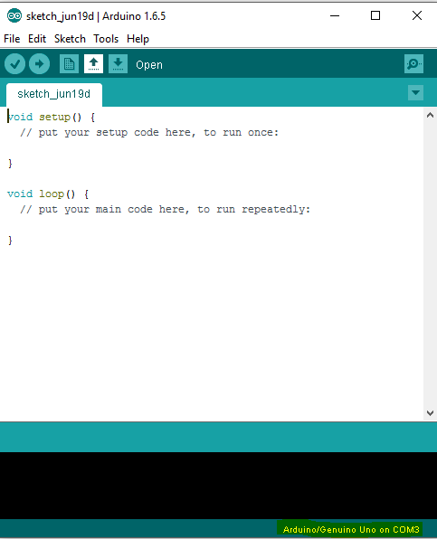
The IDE some what looks like :
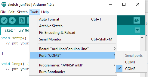
Mark the highlighted portion below, it says Arduino UNO on COM3. COM3 is a serial port id, which suggests we select the Board connection on COM3 port.
For getting on with MAC, please follow the link here
The selection is to be done under
Tools-> Port-> “Select”
The default code as you see goes like:
void setup() {
  // put your setup code here, to run once:

}

void loop() {
  // put your main code here, to run repeatedly:

}
Pretty simple to understand. It first does the set up and then the loop code gets executed in order to perform the main task you have configured. There are many sample programs inbuilt with the code, which we can find under
Files->Examples->Basic->Blink.
Run the Blink program and try to understand what has been done. It is very simple.
// the setup function runs once when you press reset or power the board
void setup() {
  // initialize digital pin 13 as an output.
  pinMode(13, OUTPUT);
    Serial.begin(9600);
}

// the loop function runs over and over again forever
void loop() {
  digitalWrite(13, LOW);   // turn the LED on (HIGH is the voltage level)
  delay(1000);              // wait for a second
  digitalWrite(13, HIGH);    // turn the LED off by making the voltage LOW
  delay(1000);              // wait for a second
}
Here, the pinMode function activates the pin which you specify as input or output. Here it is Pin 13 and is Output. Pin 13 is as we all know the default LED. Here it sets the pin and then in loop method, we find the method with digital-Write prefix, which says that the connection is on the Digital pins. The method, which we see has the Pin port number and the other parameter as LOW/HIGH which can be considered as 1/0 in order to light up and light off the LED 13. Delay has been given, to mention the Led light up with the specified delay time.
Before, checking build up which we will be making in the due course, lets have look at the other components to be used.
1. Bread Board:- The board which is familiar to all electrical or engineering students also.
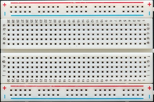
Still lets have a brief of this. As we see in the image, + symbol, meaning the voltage connection to be done to this port. The entire line, column wise is connected. Every whole in the plus column is connected internally. You can use a multimeter to check and verify the bread board.
Same applies for the – symbol column. But, this is usually used for the grounded pins connection from the Arduino. The a,b,c,d.. columns are used to connect the Leds and the resistors, which we will see in a while. Unlike the +/- these are connected internally ROW-WISE.
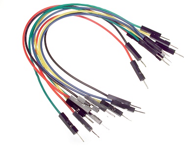
2. Jumper Wires:- These are the connecting wires to be used in order to connect the arduino and the bread board ports. They are cheap and reliable as well. They look like:
3. Few LEDs and resistors.
Next is to design our circuit, which looks like:
The above is the basic bread board connection circuit. I will give a pictorial image of the entire circuit connection. In this article I will be sharing how to take user inputs through the Serial port and use it to Lid on and off the LED. The circuit connection looks like below:-
The connection diagram goes below:
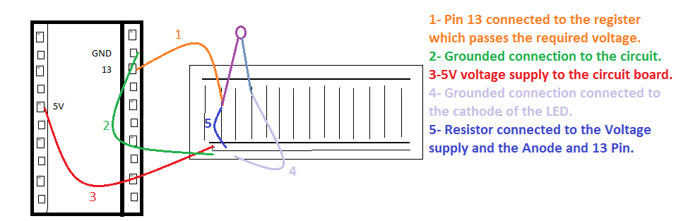
The above diagram is a reference. For any doubt you can add your queries related to the connections.
As you have seen, I have used Pin 13 to connect the Arduino program to the Bread board. That is the programming uploaded will be used to manipulate the LED on/off via Pin 13. Lets have a look at the code involved:
int userInput = 0;
// the setup function runs once when you press reset or power the board
void setup() {
  // initialize digital pin 13 as an output.
  pinMode(13, OUTPUT);
    Serial.begin(9600);
}

// the loop function runs over and over again forever
void loop() {
   if (Serial.available() > 0) {
                // read the incoming byte:
                userInput = Serial.read();

                // say what you got:
                Serial.print("Received Input: ");
                Serial.println(userInput, DEC);
        }
        if(userInput==49){ //As checked through, if 1 is pressed, the result comes to be 49 based on the ASCII code
         digitalWrite(13, HIGH);   // turn the LED on (HIGH is the voltage level)
         delay(1000);  // wait for a second
        }else{
            digitalWrite(13, LOW);    // turn the LED off by making the voltage LOW
            delay(1000);   // wait for a second
        }
}
Thus the above code is simple to understand. We have used the Serial port to track the user input, which is a part of the Arduino IDE.
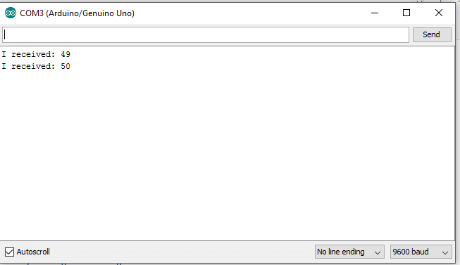
Here, the user adds the input and our code checks, if 1 with ASCII code 49, is hit then the LED lids ON and any other key pressed the LED goes OFF.
Conclusion
We have covered brief introduction about Arduino board and the circuits involved and basic programming uploaded to the Arduino board via Arduino IDE. This same concept can be integrated to
This is it all folks! I really found this interesting and this is surely the future! IOT is the future. I wish to come up with more sensors attached and programming done! I will do my homework! It would be great if all developers start throwing their hands on this and create miracles!! Share your experience and also please rectify me if I am wrong! I am still in the womb.