Introduction
Hey folks! Another interesting topic to discuss and share! Integrating sensors to an Arduino board seems interesting and feels good when you receive the desired digital output and manipulate it. Now a days hundreds of different kinds of sensors are available in the market, we need to try out and explore how we can better user experiences using these electronics. Temperature monitoring sensors, obstacles detection sensor, soil moisture detection sensors, heart pulse rate sensors and many more. I will try and use as many as sensors as I can and try integrating them with more sophisticated devices. In this article I would be sharing about the IR Obstacle sensor, which as the name suggests detects object or any obstacle coming the sensors way! Lets see how.
The sensor
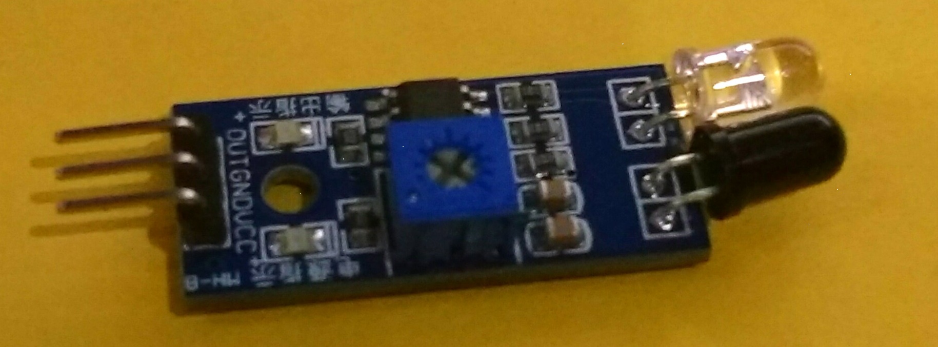
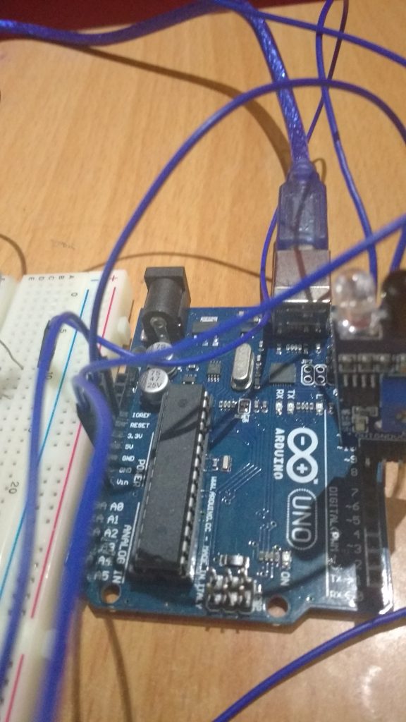
Here is how the sensor looks like. We will see another pictorial representation of the above sensor and discuss about the details of the part.
The pictorial goes like below:
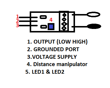
Lets learn and see what the sensor has. As you can see the numbers are mentioned, we will discuss the work around and try understand each and every word. First one goes like:
| Sensor Parts | Functions |
| OUTPUT | This port in the sensor, sends the digital out put to the output unit. Here, we have the sensor output port on board as 7. |
| GND | This port is used to connect to the board’s Grounded port. |
| VCC | The voltage supply port, here we have used the 5 V supply port from the board. |
| Distance Manipulator | The CW (Clock wise) movement increases the distance proximity and the vice-versa decreases. |
| Power and Obstacle LED | Former illuminates when the Power is supplied and the latter when any obstacle comes over. |
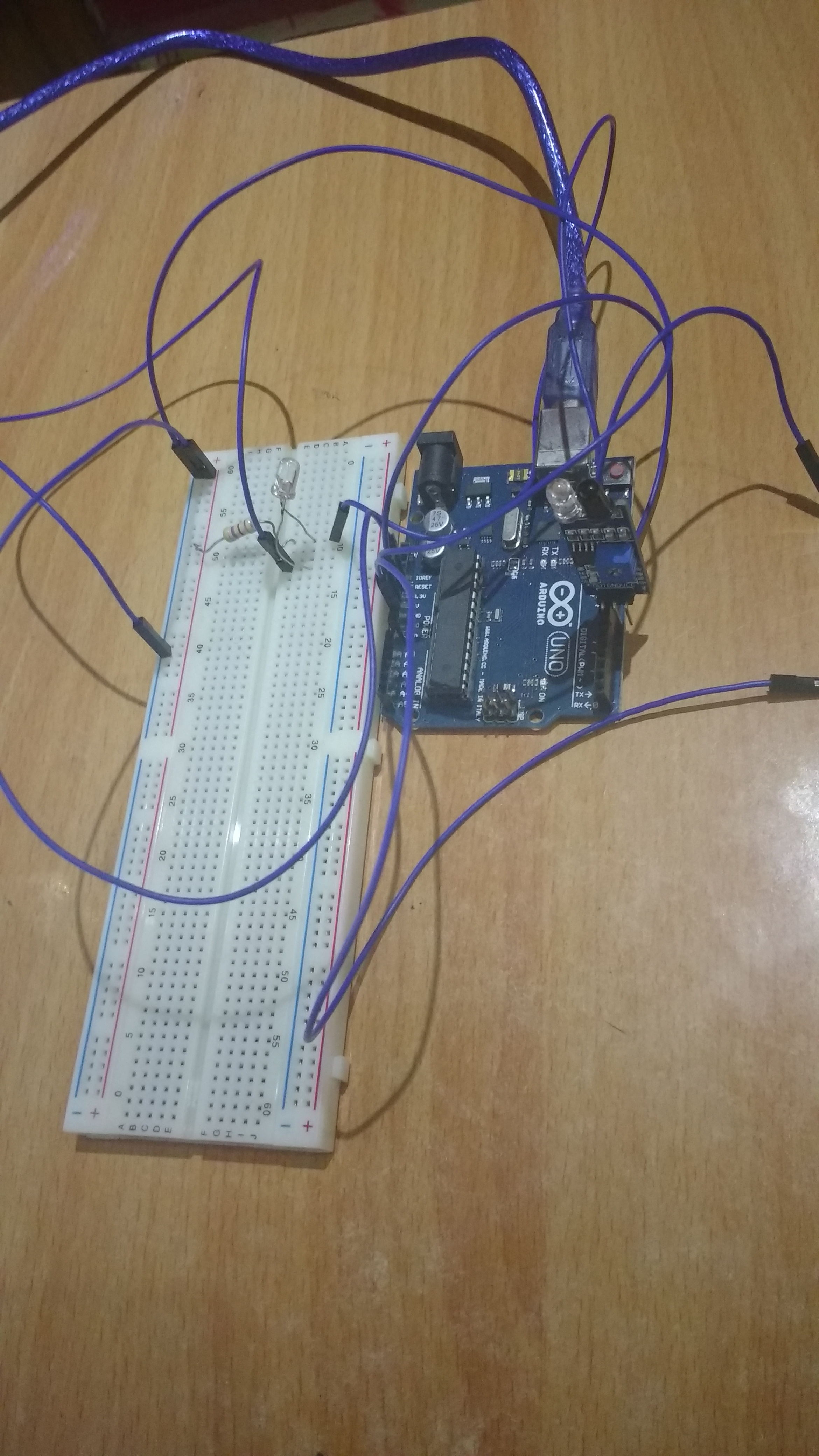
The circuit board looks like below:
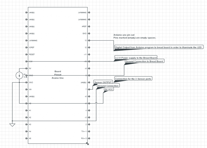
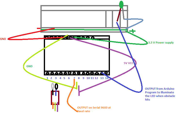
The circuit diagram would look like below:
Thats similar to the previous LED connection of my Arduino series. Series I
If the above is not clear, please share your query in the comments.
Better view of the diagram is below:

Snippet
|
1 2 3 4 5 6 7 8 9 10 11 12 13 14 15 16 17 18 19 20 21 22 23 |
int LED = 13; // Use the onboard Uno LED int obstaclePin = 7; // This is our input pin int hasObstacle = HIGH; // HIGH MEANS NO OBSTACLE void setup() { pinMode(LED, OUTPUT); pinMode(obstaclePin, INPUT); Serial.begin(9600); } void loop() { hasObstacle = digitalRead(obstaclePin); //Reads the output of the obstacle sensor from the 7th PIN of the Digital section of the arduino if (hasObstacle == LOW) //LOW means something is ahead, so illuminates the 13th Port connected LED { Serial.println("Stop something is ahead!!"); digitalWrite(LED, HIGH);//Illuminates the 13th Port LED } else { Serial.println("Path is clear"); digitalWrite(LED, LOW); } delay(200); } |
The Flow
When the full circuit is done and the code set is also done. Now, time to connect the Board to the Computer using the USB jack. Once connected to suppose COM3 port, open the Arduino Set up IDE where the code set up is done, compile the code once and then Upload the code to the Board. Once Upload is done the TX RX leds blinks quick.
Now we are all set to test the sensor. For better and precise testing, we can solder the wires (jumper wires) to the sensors as their connected pins are not portable. The whole set up can be soldered.
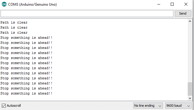
Then when we connect, open up the Serial port screen which transmits at 9600 bits per sec and check the message, as per written in the program.
As per the program, the LED also blinks and illuminates based on the Obstacle sensor output.
The serial screen would look like below:
That’s it folks!!
Conclusion
Now this is all about the sensor IR Obstacle sensor which you can purchase at a very cheap rate from ebay or amazon and play with. We can use this set up in our Cars and check out!! In the upcoming series I will be sharing more sensors and blue-tooth module integration with Arduino. Hope they will be more fun! Please share your experiences and suggestions as I am still crawling..:P